Guide to Twin Systems and Troubleshooting Error Codes

Optimise the performance of your Groeneveld twin system and ensure smooth machinery operation with our comprehensive guide. Learn how to troubleshoot common issues, improve your system's efficiency, and keep your machinery running smoothly.

What's on this page

Key Features

  • The Twin Greasing System will automatically grease all connected grease points on a timed basis (cycle) with a metered quantity of grease.
  • The system performs all operations. After the ignition is switched on at pre-defined intervals supplying measured quantities of grease from metering units to its connected grease points. Once powered up the Twin-3 display indicates the active duty mode.


In-Cab Display

NumberNameExplanation
1Switch buttonThe desired operation/test mode can be selected using the switch-button
23-Digit displayThe Twin-3 display has a 3-digit screen, which can display errors, active duty mode, and test mode
3Decimal dotThe interval timer status can be determined by the decimal dot, whether it remains active or is on standby
4System activation indicator LEDThe Green LED indicates that the system is activated
5Low grease level indicator LEDThe Yellow LED indicates when the minimum grease level has been reached
6Alarm indicator LEDThe red LED indicates at malfunction

Changing the duty mode

If applicable, the desired duty mode (light, medium or heavy duty) can be selected as follows:


NOTE: Light, medium and heavy duty interval mode contains pre-programmed times, to suit your vehicle/ application, which are changeable only with the use of Groeneveld PC-GINA software.

With the switch-button at the Twin-3 display:

  1. Switch ignition ON
  2. Push the switch-button for at least 5 seconds. Accordingly, the 3-digit display starts flashing
  3. Push the switch-button repeatedly until the desired duty mode shows
  4. Leave the desired duty mode flashing for at least 6 seconds until the duty mode comes This will confirm the desired duty mode has now changed.
  5.  

Single cycle test

In order to check the system, perform a single greasing cycle as follows with the test push-button at pump:

  • Switch ignition ON
  • Push the test push-button at pump for 3-5 The system will operate a single greasing cycle.
  • During the operation the green LED at Twin-3 display or signal lamp at the duty mode push-button will flash slowly (2-sec. on / 2-sec. off).
  • A code “T1” and a running-decimal-dot will be indicating its pump, pressure retaining, and pressure decrease phase at Twin-3 display
  • When the single greasing cycle is finished, the pump reverts to automatic mode and shows its active duty mode at Twin-3 display or signal lamp at the duty mode push-button will go off.

NOTE:

A test cycle can only be initiated when the system is NOT in an automatic pump cycle. The automatic pump cycle must complete its cycle first before any test cycles are performed.

Switching ignition off and on again or resetting the system will not reset the pump until after cycle is complete.

Multiple cycle test

In order to provide additional grease to all grease points i.e. after cleaning the vehicle or to purge the system, perform a multiple grease cycle as follows:

With the test push-button at pump:

  1. Switch ignition ON
  2. Push the test-button at pump for 6-10 seconds. The system will operate a multiple greasing cycle.
  3. During the operation the green LED at Twin-3 display will flash quickly (0,2-sec. on / 0,2-sec. off).
  4. A code “T2” and a running-decimal-dot will be indicating its pump, pressure retaining and pressure decrease phase at Twin-3 display.
  5. The multiple greasing cycle can be finished by simply switching ignition OFF.

NOTE:

Multiple cycle test should never be allowed to run longer than 30 mins in any hour. Never run multi-cycle test if system has alarmed without first establishing if grease is flowing from pump. In either case, failure to adhere to these instructions could cause serious pump damage.

Resetting the system

When the system has failed to operate and diagnostics has lead to a successful resolution, the system needs a reset in order to revert to its automatic operation mode.

Carry out a reset as follows using the test push button at pump;

  1. Push the test button for 1 second. The Twin-3 display will revert to its active duty mode and green LED comes on.

Filling the reservoir

If the yellow LED and LO code at Twin-3 display lights up continuously or the signal lamp at the duty mode push-button flashes for 2 minutes (0,5 sec. on/0,5 sec. off) at the start of each cycle, the minimum greasing level in reservoir has been reached. In this case the reservoir requires a refill as follows:

  1. When a new filler pump or hose is used, ensure no air is left in filler pump unit or hose. Prime filler pump and hose to avoid air-pockets being pumped into Twin-3 pump reservoir.
  2. Remove the dust cap from the filler coupling.
  3. Carefully clean the filler coupling and coupling on the filler hose used.
  4. Fix the filler hose on the filler coupling.
  5. Fill the reservoir up to maximum level indicated on the reservoir.
  6. The bottom of follower plate should line up with max. level mark.
  7. Remove the filler hose and fit the dust cap.
  8. Fix the filler hose on filler coupling of the filler pump, in order to keep the filler hose clean.

NOTES:

  1. The yellow LED and LO code at the Twin-3 display or signal lamp of duty mode push-button will go OFF automatically when pump reservoir  has been refilled.
  2. The reservoir does not need to be filled until the low level warning comes on at the Twin-3 display. Allowing the reservoir to drain to low level ensures no hardening of unused grease in reservoir occurs.

Grease recommendations

Grease should not contain graphite, copper, aluminum or PTFE (TEFLON). The use of correct grease in theTwin-3 system is of utmost importance. The use of grease with a maximum of 5% molybdenum disulphide (MoS2) is permitted. Groeneveld recommends the use of its GreenLube range of greases, EP-2 or ZW-0

Contact us prior to change of grease (specifications) or any other inquiries you may have.

The Twin greasing system is developed for use with grease up to NLGI-class 2. Which NLGI-class has to be used, mainly depends on the temperature in which the greasing system has to operate.

Minimum operating temperature of the systemMaximum operating temperature of the systemPrescribed NLGI Grade
-20°C / -4°F+70°C / +158°F2 EP-2 Grease 18kg pail

Periodic checks

  1. Check the grease level in the reservoir and its condition. Do not fill the reservoir until the low level warning comes on at the Twin-3 display
  2. Check the functionality of the Twin-3 display.
  3. Check if the selected duty mode is applicable to working conditions of the vehicle;
  4. Check the pump for damage and leakage;
  5. Check the primary and secondary lines for damage and leakage;
  6. Check the condition of the grease points served by the system. Sufficient fresh grease should be present; Moist Points
  7. Check system operation. Perform a single grease cycle test;
  8. Clean the pump and its surroundings;
  9. Replace or clean the internal pump filter every 500 hrs (vehicle operating/ driving hours).

The filter is located behind the external filler coupling beneath the reservoir.


Display Indicators and Error Codes

CodeLEDExplanation
Groeneveld Code
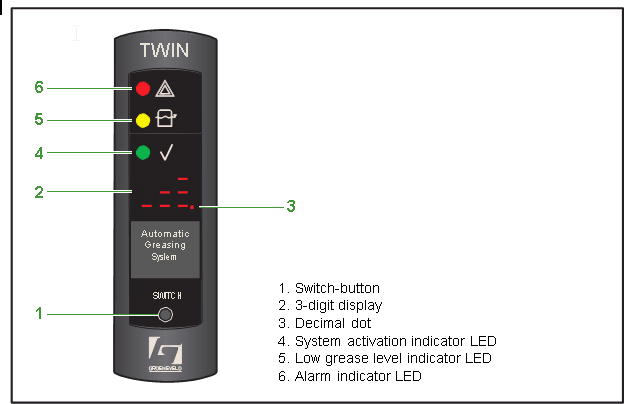
When ignition is switched ON the 3-digit display forms a rotating clock, indicating it’s communicating with the pump control unit. After 10 seconds the preset duty mode selection appears along with the green LED.
Groeneveld Code Light DutyLight duty - Greasing mode with long intervals. (Decreased greasing output)
Medium duty - Greasing mode with medium intervals. (Normal greasing output)
Heavy duty - Greasing mode with short intervals. (Increased greasing output)
Pump performs a single cycle test (LED flashes slow). (See “Single greasing cycle test” on page 6).
Pump performs multiple cycle test (LED flashes fast). (See “Multiple greasing cycle test” on page 7).
Preset amount Fast Automatic Cycles is being executed.
Minimum level in the reservoir has been reached. Resets itself by refilling the reservoir.
System error. Duty cycle selection possible only after the error has been solved. (See “Twin-3 display error codes” on page 11).
E11 due to successive no pressure in line-A
E12 due to successive no pressure in line-B
E13 due to successive pressure before cycle in line-A
E14 due to successive pressure before cycle in line-B
E15 due to empty reservoir
E20 due to successive low supply voltage
E21 due to successive faulty pressure switch circuit
E22 due to successive pump open loads
E23 due to successive pump over current
E24 due to successive valve 1 open loads
E25 due to successive valve 1 over current
E31 due to successive valve 2 open loads
E32 due to successive valve 2 over current
E50 due to a communication error with the control unit
E51 due to a parameter checksum error
E52 due to a low clock battery
E53 due to clock error
E99 due to unknown cause. This error indication shows when pump motor is disconnected due to a number of successive errors but no additional info available on the error cause. Twin pumps manufactured before September 2010 cannot provide such information to the Twin- 3 display.
Decimal dot lights up. Interval timer stop.
Decimal dot flashes. Interval timer run


Decimal dot running. Pump phase active (incl. pressure retaining and pressure decrease phase)

Share our post

Facebook
Twitter
LinkedIn

Leave a Comment

Your email address will not be published. Required fields are marked *